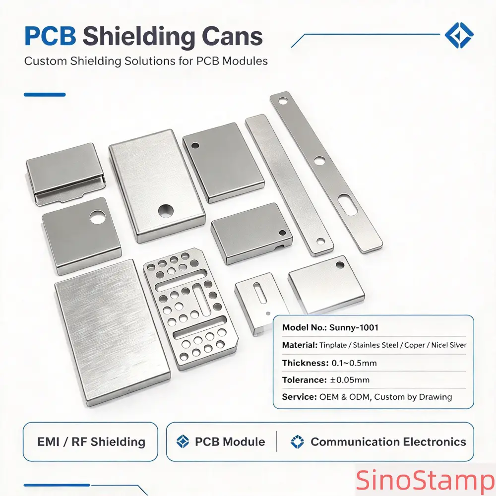

PCB shielding cans are precision metal components designed to help reduce electromagnetic interference around sensitive circuits and electronic components on printed circuit boards. They are widely used in wireless communication modules, Bluetooth devices, WiFi equipment, RF circuits, consumer electronics, industrial control systems, and other electronic products where electromagnetic compatibility is an important design consideration.
As electronic products become increasingly compact and integrated, circuit boards often contain multiple electronic components operating at different frequencies and signal levels. Unwanted electromagnetic coupling between circuits can affect product performance, signal stability, and electromagnetic compatibility. A properly designed PCB shielding can provides a conductive enclosure around selected circuit areas to help control electromagnetic interference.
SinoStamp supplies custom PCB shielding cans for international OEM manufacturers, electronic component companies, PCB assemblers, and product development teams. We focus on customized precision metal stamping components manufactured according to customer drawings, samples, and technical specifications.
Our PCB shielding can solutions can be customized in different shapes, dimensions, material thicknesses, wall structures, mounting features, openings, and surface finishes. Depending on the application, material options may include tinplate, stainless steel, copper, and nickel silver. Manufacturing processes can include precision blanking, punching, bending, deep drawing, forming, and other suitable metalworking operations.
Whether your project requires a simple PCB shielding cover, a removable shielding can with a separate frame, or a customized RF module enclosure, selecting the right structure and manufacturing process is essential. SinoStamp works with OEM customers to evaluate component requirements and coordinate practical manufacturing solutions for prototype development and repeat production.
PCB shielding cans are metal covers installed over selected sections of a printed circuit board to help reduce electromagnetic interference (EMI) and radio frequency interference (RFI). They form a conductive barrier around sensitive electronic circuits and may be connected to a PCB ground structure through soldering, mounting tabs, or other electrical contact arrangements.
Electronic components such as RF transceivers, oscillators, amplifiers, switching circuits, processors, and wireless communication modules can generate or respond to electromagnetic energy. When several circuit functions operate close together on the same PCB, unwanted coupling may occur between components or circuit sections.
A PCB shielding can helps create a more controlled electromagnetic environment around the protected area. The metal enclosure can reduce electromagnetic coupling, but its effectiveness depends on the complete design, including the material, geometry, enclosure continuity, openings, grounding, and installation conditions.
Unlike a general-purpose metal cover, a PCB shielding can is designed specifically for electronic circuit protection and electromagnetic compatibility requirements. Its dimensions and mounting features must match the PCB layout, component heights, ground connections, and available installation space.
PCB shielding cans are commonly manufactured through precision metal stamping and forming processes. Depending on the design, the finished component may include a top panel, sidewalls, mounting tabs, folded edges, cutouts, and other customized features.
Different electronic products require different shielding arrangements. A PCB shielding can designed for a compact wireless module may have different dimensions and mounting features from one used in an industrial communication board or a consumer electronics product.
PCB EMI shielding cans are designed to help reduce electromagnetic interference around selected circuit areas. They are commonly used when sensitive components need to be isolated from nearby electronic circuits or external electromagnetic sources.
The shielding structure may be installed over one component or a group of components. The design should consider the circuit layout, enclosure dimensions, grounding arrangement, and required assembly method.
PCB RF shielding cans are used in radio frequency applications where controlling unwanted electromagnetic coupling is important. They may be found in wireless communication modules, RF front-end circuits, receiver assemblies, transmitter circuits, and other high-frequency electronic systems.
For RF applications, the cover geometry, openings, seams, and electrical contact arrangement should be evaluated according to the operating frequency and system design. The final shielding performance should be verified through appropriate testing.
Wireless modules often integrate multiple electronic functions into a small PCB area. A custom shielding can can be designed to cover selected components while maintaining clearance for connectors, antennas, and other assembly features.
Depending on the module design, the shielding structure may include a simple one-piece cover, a removable cover, or a multi-section arrangement.
Communication equipment may contain multiple signal-processing and RF circuits that require careful electromagnetic compatibility management. PCB shielding cans can be incorporated into communication boards to help control interference between circuit sections.
Customized dimensions, material selection, mounting structures, and surface finishes can be evaluated according to the equipment design and production requirements.
PCB shielding cans can be manufactured in different structural configurations. The correct design depends on the PCB layout, component arrangement, maintenance requirements, installation method, and electromagnetic performance objectives.
One-piece PCB shielding cans are formed as a single metal component. They typically include a top surface and sidewalls, with mounting or retention features incorporated into the structure where required.
This design can provide a compact solution with fewer separate components. It may be suitable for electronic assemblies where frequent access to the protected circuit area is not required.
One-piece shielding cans can be manufactured through blanking, punching, bending, and forming operations. The tooling design should consider corner geometry, wall height, material thickness, and dimensional relationships between the top panel and sidewalls.
Two-piece PCB shielding systems generally consist of a metal frame and a removable cover. The frame is mounted to the PCB, while the upper cover can be removed when inspection, repair, or component replacement is required.
This structure is useful for electronic products that require maintenance access or allow engineering teams to inspect the protected components during development and production.
The frame and cover must be designed together to ensure suitable mechanical engagement and electrical contact. Retention features, wall height, cover fit, and mounting positions should be clearly specified in the engineering drawing.
Some PCBs contain several circuit sections that need to be separated within the same shielding arrangement. Multi-compartment shielding cans use internal partitions or separate chambers to create different shielding areas.
These structures may be used in complex RF modules, communication systems, and electronic assemblies with multiple functional sections.
Manufacturing complexity depends on the number of compartments, internal wall geometry, material thickness, forming requirements, and the dimensional relationship between different sections.
Low-profile shielding cans are designed for compact PCB assemblies where installation height is limited. They are commonly considered for portable electronics, wireless modules, communication devices, and other space-constrained products.
Low-profile designs require careful control of the overall height and clearance between the cover and the electronic components. The cover should provide sufficient structural stability without interfering with connectors, antennas, or other PCB features.
Some PCB shielding cans require openings for connectors, cables, adjustment components, or other functional elements. These openings can be incorporated into the metal structure through punching or other suitable manufacturing operations.
Opening positions and dimensions should be clearly defined in the drawing. Since apertures can influence shielding effectiveness, they should be reviewed as part of the overall electromagnetic design rather than treated only as mechanical details.
Material selection is an important consideration in PCB shielding can manufacturing. Different metals offer different electrical conductivity, mechanical strength, corrosion resistance, formability, and surface characteristics.
The most suitable material depends on the required shielding arrangement, operating environment, material thickness, forming complexity, and total project cost. SinoStamp supports several commonly used metal materials for custom PCB shielding components.
Tinplate is a steel-based sheet material with a tin coating. It is used in selected electronic shielding applications because it combines a steel substrate with a conductive surface coating and can be processed into different stamped metal structures.
Tinplate PCB shielding cans may be suitable for applications requiring a balance between material cost, forming characteristics, and surface properties. The selected substrate and coating specifications should be confirmed according to the customer's technical requirements.
During manufacturing, material thickness, coating condition, forming geometry, and edge quality should be considered. The forming process should be evaluated to avoid unnecessary damage to the coating.
Stainless steel is selected for applications where corrosion resistance, mechanical strength, and structural stability are important. Different stainless steel grades offer different forming and mechanical properties.
Stainless steel PCB shielding cans may be considered for industrial electronics, communication equipment, and other assemblies exposed to demanding operating environments.
Because stainless steel generally has lower electrical conductivity than copper, its suitability should be evaluated according to the required shielding design. Grounding and electrical contact arrangements may also require special consideration.
Copper is widely used in electrical and electronic applications because of its excellent electrical conductivity. It may be suitable for PCB shielding designs where conductive properties are an important selection factor.
Copper shielding cans can be manufactured in different customized shapes and dimensions. However, copper is relatively soft compared with some other metal materials, so tooling design, handling, and forming conditions should be considered carefully.
Customers should specify the required copper grade and material condition where applicable. These details help determine suitable manufacturing parameters and the expected mechanical characteristics of the finished component.
Nickel silver is a copper-based alloy that generally contains nickel and zinc. Despite its name, it does not contain silver. It is used in selected precision metal and electronic component applications because of its combination of mechanical characteristics, appearance, and corrosion resistance.
Nickel silver PCB shielding cans may be considered for applications requiring a particular balance of conductivity, strength, forming behavior, and surface characteristics.
The exact alloy grade should be confirmed before production because different compositions can have different electrical and mechanical properties.
When choosing material for PCB shielding cans, OEM engineers should consider the following factors:
No single material is suitable for every PCB shielding application. Material selection should be based on the complete assembly design and verified through appropriate testing where shielding performance is critical.
Material thickness affects the mechanical strength, forming behavior, weight, and dimensional stability of PCB shielding cans. A suitable thickness should provide sufficient structural rigidity while meeting the installation space and manufacturing requirements.
Thin-gauge sheet metal is commonly considered for compact electronic shielding components because it can help reduce weight and overall assembly height. However, thin materials may be more sensitive to deformation during handling and forming.
Thicker materials may offer greater rigidity, but they can require different tooling conditions and higher forming forces. The correct thickness should be selected according to the cover dimensions, wall height, corner structure, material grade, and expected production conditions.
Overall length, width, and height are important dimensions for PCB shielding cans. These measurements determine whether the cover fits within the available PCB space and provides sufficient clearance for the components underneath.
The dimensions should be based on the latest PCB layout and mechanical design. Any changes to component positions or board dimensions should be reviewed before tooling modification or repeat production.
Wall height affects the available internal clearance and the mechanical structure of the shielding can. The sidewall design should consider the height of the protected components and the required contact arrangement with the PCB or frame.
Corner radii, bend angles, wall straightness, and formed features should be evaluated during the manufacturing review. These factors influence the final fit and dimensional consistency.
Mounting tabs, soldering features, retaining edges, and other contact structures may be critical to the installation of a PCB shielding can. Their positions should match the PCB layout and the selected assembly process.
Critical dimensions should be identified in the engineering drawing. Tolerances should be assigned according to functional requirements and realistic manufacturing capabilities.
Precision metal stamping is widely used to manufacture PCB shielding cans with repeatable dimensions and customized structural features. The manufacturing process is selected according to material properties, part geometry, required tolerances, and production quantity.
Blanking cuts the initial metal profile from sheet or strip material. The blanking operation establishes the basic outline of the shielding can and provides the starting shape for subsequent forming operations.
The blanking layout should consider material utilization, part dimensions, edge quality, and the position of features that will be formed later.
Punching creates holes, slots, and other openings in the metal component. PCB shielding cans may require openings for connectors, mounting points, alignment features, or other assembly requirements.
Hole dimensions and positions should be controlled according to the engineering drawing. For shielding applications, openings must also be considered in relation to the electromagnetic design.
Bending is used to create the sidewalls, flanges, and other angled features of a shielding can. It transforms a flat blank into a three-dimensional structure that can fit over the required PCB area.
Material thickness, bend radius, material direction, and springback influence the final geometry. These factors should be considered during tooling design and sample evaluation.
Deep drawing is a forming process used to produce three-dimensional metal structures by drawing sheet material into a die cavity. Depending on the material and geometry, it can be considered for shielding components with deeper or more complex formed profiles.
Deep drawing suitability depends on material ductility, thickness, draw depth, corner radius, and the overall geometry. Not every PCB shielding can requires deep drawing; simpler structures may be manufactured more economically through blanking and bending.
Precision forming is used to create additional structural features such as raised sections, retaining edges, embossments, and customized profiles. These features can support mechanical stability and assembly compatibility.
The forming sequence should be evaluated to reduce excessive material stress and maintain the required dimensions.
Progressive die stamping combines multiple operations into a single tooling system. A metal strip passes through several stations, with each station performing a specific cutting or forming operation.
This method may be suitable for PCB shielding cans with repeated features and stable production demand. It can improve production efficiency after tooling development and process stabilization.
The choice between progressive die stamping and separate stamping operations depends on the part geometry, tooling investment, production volume, and expected long-term demand.
Custom PCB shielding cans often require dedicated tooling to achieve the required dimensions and structural features. Tooling development is an important stage because it influences manufacturing consistency, production efficiency, and the overall project cost.
Before tooling begins, the customer and manufacturer should review the engineering drawing, material specification, thickness, critical dimensions, surface finish, and expected production quantity.
The initial review should identify possible manufacturing challenges, including narrow walls, small bend radii, complex openings, deep formed sections, and tight dimensional tolerances.
Where necessary, the manufacturing team may recommend adjustments to improve forming feasibility, reduce tooling complexity, or improve production consistency. Any design modification should be reviewed and approved by the customer.
Tooling design depends on the required stamping operations and component geometry. A simple cover may require relatively straightforward blanking and bending tools, while a more complex shielding structure may need multiple forming stations or progressive tooling.
Tooling investment should be evaluated in relation to the expected order quantity and repeat production plan. For projects with long-term demand, dedicated tooling may provide better consistency and production efficiency.
Initial tooling trials help verify the manufacturing process and finished component dimensions. Sample parts can be inspected against the approved drawing before regular production begins.
Customers should confirm the sample approval criteria, critical measurements, and any required assembly checks. Changes identified during sample evaluation should be resolved before mass production approval.
For repeat orders, tooling condition and maintenance are important factors in maintaining consistent product quality. The maintenance plan should consider production volume, tool wear, material characteristics, and the complexity of the component.
Tooling ownership, maintenance responsibilities, storage arrangements, and modification costs should be clarified before the project begins.
Surface finishing can influence the corrosion resistance, appearance, solderability, electrical contact characteristics, and storage stability of PCB shielding cans. The appropriate finish depends on the base material and the functional requirements of the electronic assembly.
Bright tin plating provides a bright metallic surface and is used in selected electronic and electrical component applications. It may be considered where solderability, surface appearance, or contact characteristics are important.
The coating specification should identify the required plating thickness and any applicable performance requirements. Coating condition and adhesion should be considered during quality inspection.
Matte finishes provide a non-glossy surface appearance and may be selected for particular product or assembly requirements. The exact finishing method depends on the base material and the desired surface characteristics.
OEM customers should provide a clear finish specification or approved reference sample to avoid differences in appearance between production batches.
Anti-tarnish treatment may be used on selected metal surfaces to reduce discoloration during storage and handling. It can be relevant for shielding cans that need to maintain a stable surface condition before assembly.
The suitability of the treatment should be checked against the base material, coating system, and downstream assembly process.
Gold plating may be specified for certain electronic contact applications where particular contact or corrosion characteristics are required. It is not automatically necessary for every PCB shielding can.
Where gold plating is required, the coating thickness, coverage area, underlayer, and functional requirements should be defined clearly before production.
Deburring removes or reduces sharp edges and unwanted burrs created during stamping. Proper edge treatment can improve handling safety, assembly compatibility, and finished-part quality.
For PCB shielding cans, edge condition may also affect mechanical fit and contact with the supporting structure. Inspection criteria should be agreed upon according to the component function.
PCB shielding can design should consider electromagnetic performance from the beginning of the product development process. A metal cover can help reduce electromagnetic coupling, but the result depends on the complete enclosure and its integration with the PCB.
The operating frequency range is an important input for shielding design. Different frequencies interact with enclosure dimensions, apertures, seams, and material properties in different ways.
OEM engineers should identify the frequency range that needs to be controlled and provide relevant electromagnetic compatibility requirements wherever possible.
Gaps and discontinuities can create leakage paths in a shielding structure. The design should consider the interface between the cover and the PCB, frame, or other conductive components.
For removable covers, the contact arrangement should provide suitable mechanical engagement and electrical continuity under the expected assembly conditions.
Openings may be required for connectors, cables, adjustment components, or other functional features. However, aperture size and location can influence shielding effectiveness.
Openings should be evaluated as part of the overall electromagnetic design. Unnecessary openings should be avoided where they may compromise the required shielding arrangement.
Grounding provides an electrical reference and may help establish continuity between the shielding cover and the PCB ground structure. The design can use soldered tabs, conductive contacts, or other suitable arrangements.
The grounding method should be defined by the electronic design team and verified during assembly evaluation.
Shielding effectiveness is commonly expressed in decibels (dB), but a meaningful result requires a defined frequency range and test method. Measurements may vary depending on the test fixture, enclosure geometry, installation conditions, and surrounding electromagnetic environment.
Material-level shielding data should not automatically be treated as the performance of a finished PCB shielding can. Where specific performance targets exist, testing should be performed on the finished component or representative electronic assembly under agreed conditions.
SinoStamp focuses on supplying metal shielding components according to customer drawings and manufacturing specifications. Actual EMI and RF performance should be confirmed through appropriate engineering evaluation and testing of the complete assembly.
Quality control is essential for PCB shielding cans because dimensional variations, surface defects, burrs, and forming inconsistencies can affect assembly fit and electrical contact.
A suitable inspection process should cover incoming materials, tooling trials, in-process production, finishing, and final inspection.
Incoming inspection may include material grade verification, thickness measurement, surface condition checks, and batch identification. Material documentation should be reviewed according to the customer's specification.
First article inspection verifies whether the initial stamped parts meet the approved engineering drawing. Important dimensions may include length, width, height, wall position, opening dimensions, and mounting feature locations.
Where required, dimensional inspection reports can be prepared for customer review before production approval.
In-process inspection may include dimensional measurements, visual checks, burr assessment, and monitoring of forming quality. Inspection frequency should be determined according to the component complexity and quality requirements.
Final inspection may cover dimensions, surface appearance, edge condition, forming accuracy, plating condition, and packaging. Additional checks may be required for special assembly or functional requirements.
OEM customers may request inspection reports, material certificates, production batch records, and other quality documentation. These requirements should be confirmed before production so the appropriate records can be maintained.
Approved drawings, specifications, and inspection criteria should be controlled throughout the project to support consistency between initial and repeat orders.
Custom PCB shielding can projects usually begin with a technical drawing, CAD file, physical sample, or PCB assembly requirement. The manufacturer then evaluates the material, geometry, stamping process, tooling requirements, and inspection criteria.
SinoStamp supports OEM and ODM customization for metal shielding components according to customer project specifications.
Customers can provide 2D engineering drawings and 3D CAD files to define the required dimensions, material, thickness, tolerances, surface treatment, and structural features.
Clear technical drawings help reduce misunderstandings during quotation, tooling development, sample production, and repeat manufacturing.
For projects without complete drawings, customers may provide an existing shielding can sample for evaluation. A physical sample can help identify the basic geometry and structural requirements.
Additional measurements and technical confirmation may still be required before tooling development and production approval.
Different material grades and manufacturing processes may be suitable for the same general shielding structure. The final solution should balance electromagnetic requirements, mechanical properties, forming feasibility, dimensional accuracy, and production cost.
Prototype and sample production allow OEM customers to evaluate component dimensions, PCB fit, surface condition, and assembly compatibility before approving regular production.
Sample evaluation may identify necessary design or process adjustments. These should be resolved and documented before the production specification is finalized.
Small and medium batch production can be important for new electronic products, pilot projects, engineering validation, and specialized equipment. The manufacturing arrangement should consider tooling investment, setup requirements, material availability, and the expected repeat order schedule.
For projects with uncertain demand, the customer and supplier should discuss a practical production plan that balances initial investment and future supply needs.
For established OEM products, consistency between repeat orders is important. Approved drawings, material specifications, surface finishes, tooling conditions, and inspection requirements should be maintained as controlled production references.
Changes to materials, dimensions, tooling, or finishing processes should be reviewed and approved before implementation.
PCB shielding cans are used across a wide range of electronic industries. Their dimensions, materials, and structural features are customized according to the specific circuit board and final product.
WiFi modules are commonly integrated into routers, gateways, smart home products, industrial controllers, and other connected devices. Custom PCB shielding cans can help manage electromagnetic coupling around selected circuit areas.
Wireless module shielding designs may require compact dimensions, low overall height, and customized openings or mounting features.
Bluetooth modules are used in connected electronics, industrial devices, audio equipment, and smart products. Shielding cans may be integrated into the PCB design to help manage interference between different electronic sections.
RF communication boards may contain amplifiers, filters, transceivers, and other sensitive components. Custom metal shielding structures can be used as part of the electromagnetic compatibility strategy.
The cover geometry and grounding design should be evaluated according to the frequency range and complete RF system requirements.
Consumer electronic devices often require compact and lightweight PCB shielding components. Applications may include smart devices, portable electronics, audio products, and other electronic assemblies.
Industrial control boards may operate near motors, switching systems, communication equipment, and other sources of electromagnetic interference. PCB shielding cans can be incorporated into selected electronic sections where shielding is required by the product design.
Automotive electronic systems may contain communication, control, sensing, and signal-processing circuits. Certain modules use metal shielding structures as part of their electromagnetic compatibility design.
Automotive projects may have additional requirements for environmental durability, traceability, documentation, and validation. These requirements should be clearly defined before supplier selection and production.
Choosing a suitable supplier is an important step for OEM manufacturers sourcing custom PCB shielding cans. Buyers should evaluate more than the unit price. Manufacturing experience, material knowledge, tooling arrangements, quality control, engineering communication, and long-term supply capability all influence project success.
Ask whether the supplier has experience with thin-gauge metal components, precision stamping, bending, forming, and electronic shielding structures. Similar project experience can help identify manufacturing risks earlier.
Understand how tooling is designed, manufactured, tested, maintained, and stored. Confirm tooling ownership and responsibilities for future modifications before placing an order.
A capable supplier should understand the differences between tinplate, stainless steel, copper, nickel silver, and other relevant materials. Material selection should be based on actual application requirements rather than price alone.
Ask how critical dimensions are measured, how burrs and surface defects are controlled, and how plating or coating conditions are inspected. Where appropriate, request sample inspection records and material documentation.
Small and medium-sized OEM manufacturers may require prototype quantities, pilot production, and repeat orders in different volumes. Discuss expected annual demand and production schedules before finalizing the tooling and quotation arrangement.
International OEM projects require clear communication about drawings, revisions, material specifications, samples, quality requirements, and delivery schedules. A reliable supplier should be able to identify missing information and communicate manufacturing issues before production begins.
Providing complete project information helps the supplier evaluate manufacturing feasibility and prepare a more accurate quotation. Whenever possible, OEM buyers should provide the following details:
For complex shielding designs, providing the relevant PCB assembly information can help the manufacturer understand the installation structure and identify possible manufacturing concerns before tooling development.
SinoStamp focuses on customized metal stamping components for international OEM manufacturers. Our business model combines our own brand and project coordination with production resources from cooperating manufacturing partners. We work with customers to understand their technical requirements and coordinate suitable manufacturing solutions according to approved specifications.
We support custom dimensions, shapes, wall structures, openings, mounting features, and surface finishes. Components are evaluated according to customer drawings and application requirements.
Material options can include tinplate, stainless steel, copper, and nickel silver, depending on the project requirements. The final material should be confirmed according to the required electrical, mechanical, environmental, and forming properties.
Manufacturing processes may include blanking, punching, bending, deep drawing, and precision forming. The most suitable process is selected according to the component design, material thickness, tooling requirements, and production volume.
We support customer projects based on engineering drawings, physical samples, and technical specifications. Project evaluation can include material selection, tooling arrangements, sample development, manufacturing coordination, and repeat production planning.
We understand that many overseas OEM manufacturers need flexible sourcing arrangements for customized metal components. Project requirements may include initial sample orders, small or medium production batches, and long-term repeat purchasing.
Our focus is to provide clear communication and coordinated manufacturing support throughout the project lifecycle.
PCB shielding cans are important metal components for electronic assemblies where electromagnetic compatibility and circuit protection need to be considered. They help create conductive enclosures around selected circuit areas and can be customized according to the PCB layout, operating environment, and mechanical installation requirements.
Successful PCB shielding can development requires careful consideration of material selection, cover geometry, thickness, openings, grounding, surface finishing, tooling design, and dimensional inspection. The final shielding performance depends on the complete assembly and should be verified through appropriate testing.
Precision metal stamping provides flexible manufacturing options for different PCB shielding structures, from simple one-piece covers to removable two-piece systems and multi-compartment designs. The manufacturing process should be selected according to component geometry, production quantity, and long-term supply requirements.
SinoStamp supplies customized PCB shielding cans for OEM manufacturers, PCB assemblers, communication equipment companies, and electronic product developers. We support project evaluation based on customer drawings, samples, material specifications, and manufacturing requirements.
If you are looking for a China-based PCB shielding cans supplier for your next electronic project, you are welcome to prepare your engineering drawings, PCB layout, material requirements, surface finish specifications, and estimated order quantity. These details will help us evaluate your project and discuss a suitable custom metal stamping solution.
```