Sunny-1003 Electronic Metal Brackets: Custom Stamped Mounting Solutions for PCB and Component Assembly
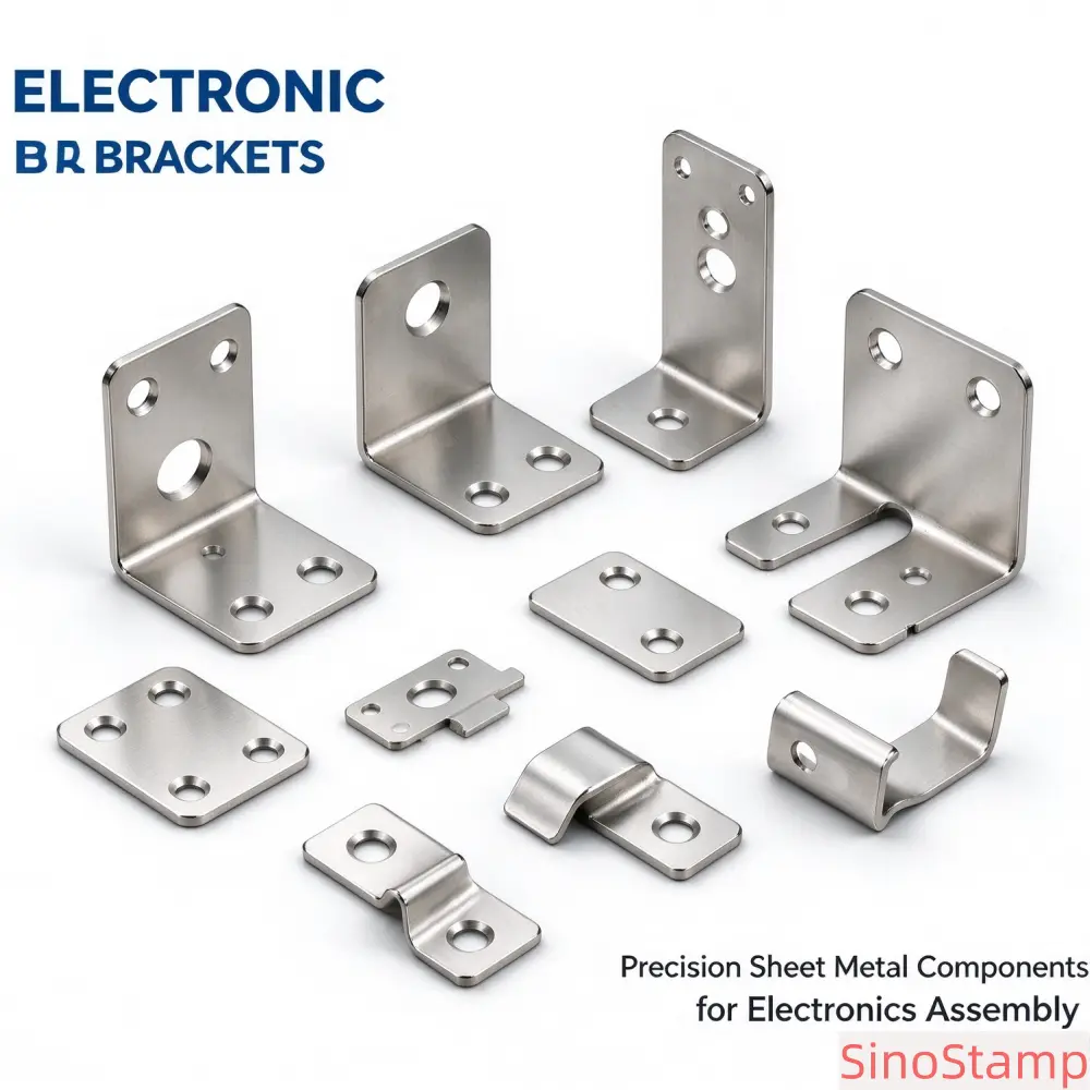
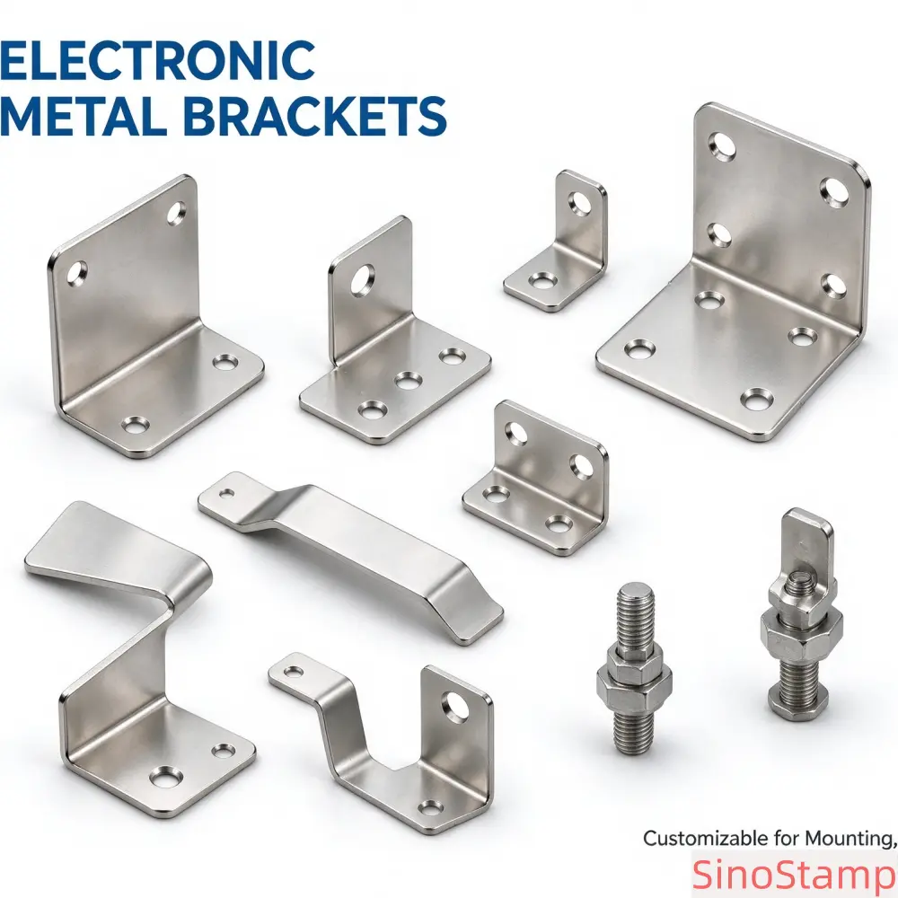
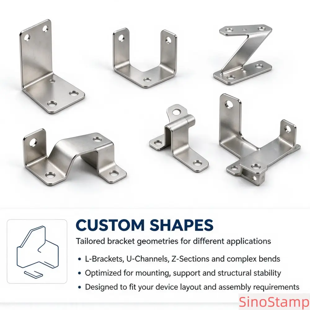
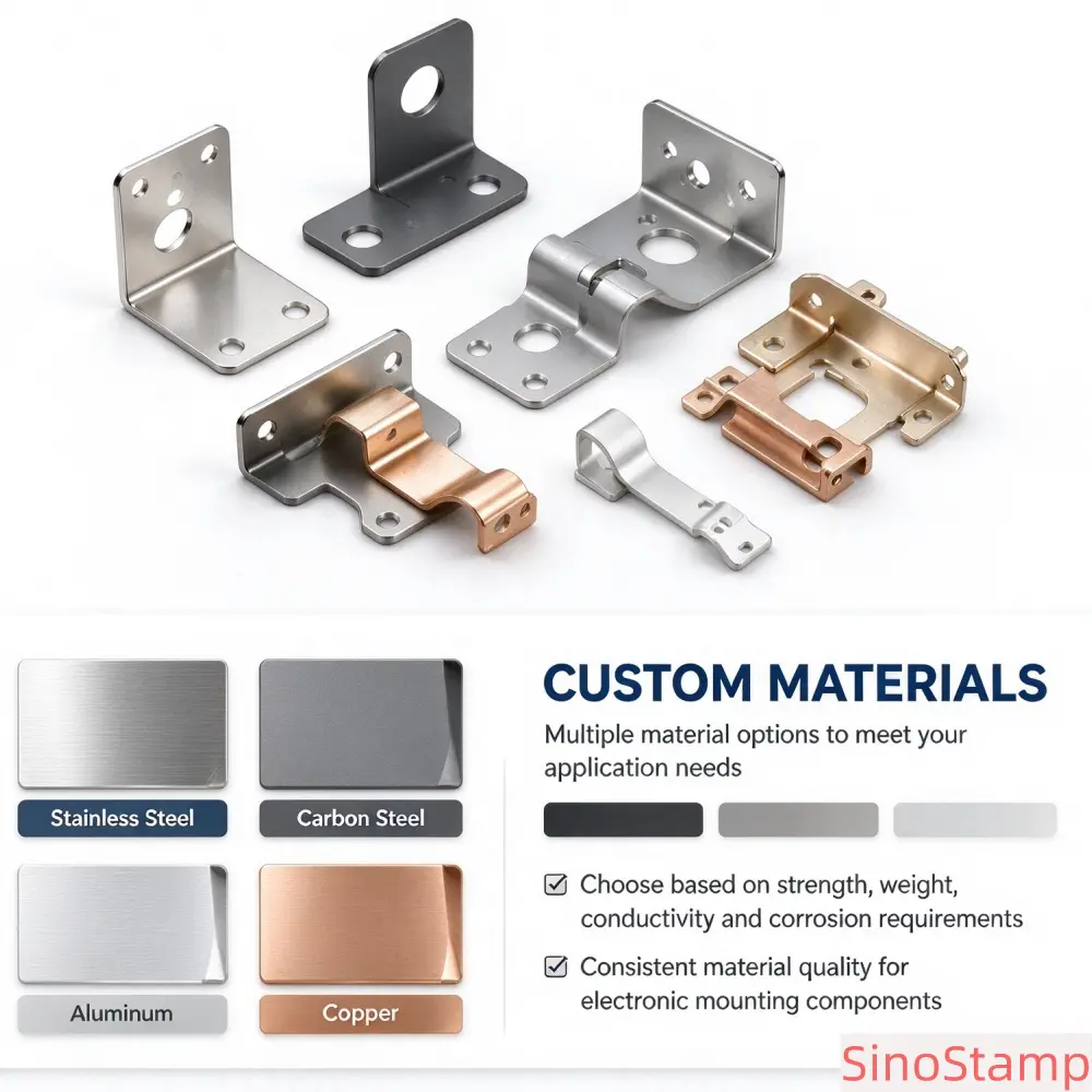
Sunny-1003 is a custom-manufactured electronic metal bracket produced by SinoStamp, a China-based precision stamping and sheet metal fabrication supplier. The part is built to customer drawings and samples rather than from a fixed catalogue, which means the material, thickness, hole pattern, bend geometry, tapping and riveting features, and surface finish are all defined by the assembly it has to serve. The bracket family covers stainless steel, aluminum, tinplate and copper, with a working thickness range of 0.3 mm to 3.0 mm and a critical-dimension tolerance of ±0.05 mm where the drawing identifies a functional datum. Typical applications include PCB mounting, power supply internal support, communication equipment assembly and household appliance structures.
For a B2B buyer, an engineer or an OEM project team, the relevant question is not whether a supplier can produce âa bracket.â The relevant question is whether the supplier understands how a bracket behaves after forming: how a hole moves when it sits near a bend line, how a powder-coated surface changes the electrical path to ground, how a self-clinching fastener interacts with panel thickness, and how a process stays capable across a production run rather than only on the first sample. The sections below address these questions in the order a technical buyer typically evaluates them.
Specifications at a Glance
Model No.: Sunny-1003. Product Name: Electronic Metal Brackets. Material: Stainless Steel / Aluminum / Tinplate / Copper (Customizable). Thickness: 0.3 mm â 3.0 mm (Customizable). Surface Finish: Zinc plating / Nickel plating / Powder coating / Matte. Processing: Precision stamping, bending, forming, tapping, riveting. Function: Support, fix and secure PCB boards and electronic components. Tolerance: ±0.05 mm for critical dimensions. Certification: RoHS, ISO9001, CE. Packing: Anti-static bag + export carton.
Tighter tolerances, alternative material grades, custom hole patterns and bend angles are available by drawing review. The specification list should be read together with the technical sections that follow, because several of the listed items interact: a surface finish that protects the part may also interrupt a grounding path, and a tolerance callout that is appropriate for an assembly hole may be unnecessary and costly if applied to a cosmetic edge.
What Separates an Electronic Bracket from a General Structural Bracket
A general structural bracket is judged primarily by strength and fit. An electronic bracket is judged on a wider set of criteria because it sits inside a product that has electrical, thermal and assembly requirements. The bracket must position a PCB or a component within a defined envelope, maintain that position through handling and vibration, provide a reliable electrical path to ground where the design calls for one, survive the surface finishing process without losing that path, and remain dimensionally stable from the first article to the last unit in the order.
These requirements are not independent. A bracket that is dimensionally correct but has an uninterrupted powder coating over its grounding pad will fail electrically. A bracket with a properly masked grounding area but a hole placed too close to a bend line may deform during forming and no longer accept the mating fastener. A bracket that passes a first-article inspection but has a bending process with excessive springback variation will drift out of tolerance across a volume run. The engineering value of a stamped bracket supplier is the ability to recognize these interactions at the drawing-review stage, before tooling is cut and before a purchase order is placed.
Materials: Selecting the Grade, Not Just the Family
The material families listed for Sunny-1003 are stainless steel, aluminum, tinplate and copper. Each family contains grades with materially different forming behavior, and the grade selection has a direct effect on bend radii, springback compensation, tooling wear and surface finish compatibility.
Stainless Steel Brackets
Stainless steel is selected when corrosion resistance and structural durability are the dominant requirements. The common stamping grades are 304 and 316, with 304 covering the majority of electronic enclosure and mounting bracket applications and 316 reserved for more aggressive environments where chloride exposure or cleaning chemistry is a factor[reference:0]. Stainless steel work-hardens during forming, and its springback is higher than low-carbon steel, which means the bend angle requires more compensation and the tooling must account for the material's recovery after the punch is released. Minimum bend radii for stainless steel 304 are typically in the range of one to one and a half times material thickness, and forming along the rolling grain direction increases the risk of outer-surface cracking[reference:1]. For a bracket with multiple bends, this springback behavior accumulates, and a three- or four-bend part can drift further from nominal than a single-bend part even when each individual bend is within its own tolerance[reference:2].
Aluminum Brackets
Aluminum is selected for weight reduction and for parts that need to conduct heat or electricity. The two grades most frequently specified in electronic bracket work are 5052 and 6061. Alloy 5052 in the H32 temper has good formability with a minimum bend radius close to one times thickness, while 6061 in the T6 temper is harder and typically requires a minimum inside radius of two to three times thickness[reference:3]. A buyer who specifies âaluminumâ without a grade and temper may receive a quote based on 5052 and then discover that a drawing intended for 6061-T6 cannot be formed at the same radius without cracking. Aluminum also requires attention to surface treatment compatibility: anodizing is common on aluminum brackets, but if the bracket has a grounding function, the anodized layer is electrically insulating and the grounding contact area must be masked or left unfinished.
Tinplate Brackets
Tinplate is a low-carbon steel with a thin tin coating, selected where cost and solderability matter more than long-term corrosion resistance. It is common in high-volume consumer electronics and appliance brackets that sit in a controlled indoor environment. The tin coating supports soldering and provides a degree of contact conductivity, but the coating is thin and the cut edges expose the steel substrate, so the corrosion protection is limited compared with stainless steel or a post-plated finish. When a drawing specifies tinplate, the buyer should confirm the base steel grade, the tin coating weight and whether the part will be formed after coating, because forming a pre-coated material can damage the coating at the bend radius.
Copper Brackets
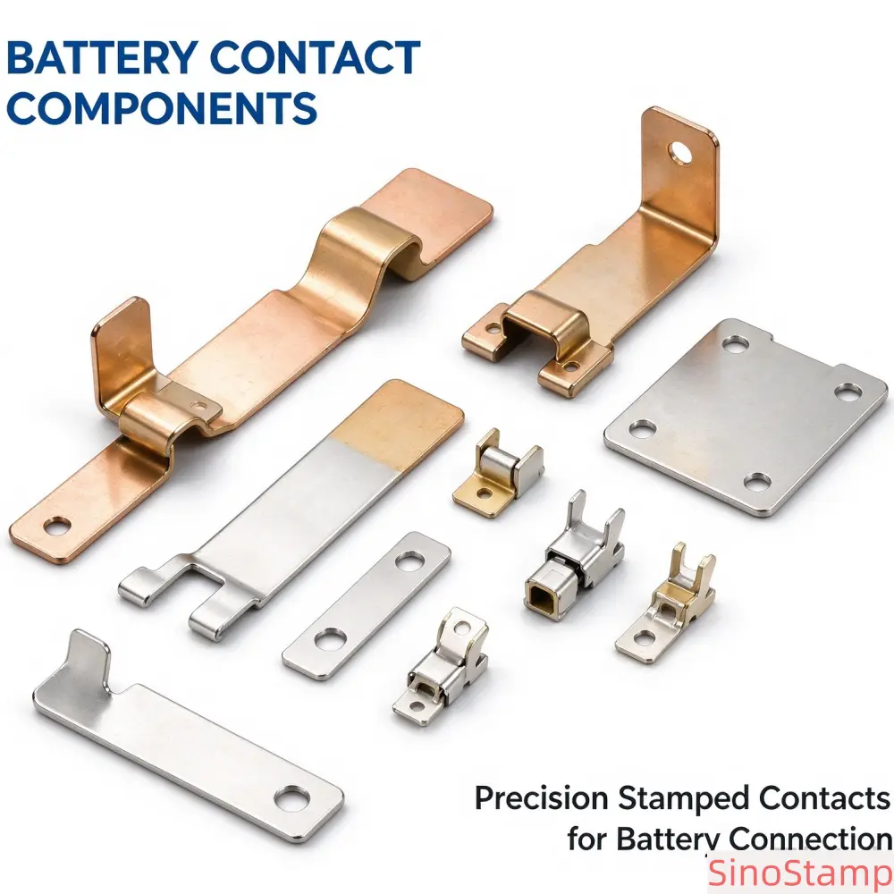
Copper is selected where electrical or thermal conductivity is the primary function rather than a secondary benefit. Copper and copper alloys such as C11000 are used for grounding brackets, conductive mounting interfaces and parts that must carry current or dissipate heat[reference:4]. Copper is soft and highly formable, but its springback behavior differs from steel, and tight bend radii or deep-formed features require a grade and temper review. Bare copper tarnishes readily, so an anti-tarnish treatment or a plated finish is often applied, and the finish selection must be checked against the conductivity requirement at the contact area.
Forming Behavior: Bend Radius, Springback and Hole Displacement
The thickness range of 0.3 mm to 3.0 mm covers a wide band of forming conditions, and the same bracket geometry does not behave identically across that range. Thin-gauge material is easier to cut and pierce but is more sensitive to distortion near bends. Thick-gauge material requires higher forming force, produces more springback, and places greater demand on tooling rigidity and press capacity.
The most frequent dimensional problem in stamped brackets is hole displacement caused by bending. A hole that is pierced in the flat blank before bending does not necessarily remain at its nominal position after the bend is formed. Research on forming processes has shown that hole position sometimes cannot be held to tolerance when a workpiece is pierced before bending, because the material flow during the bend displaces the hole[reference:5]. The practical design rule is to keep the hole at a safe distance from the bend line: at least 2.5 times material thickness plus the inside bend radius from the start of the bend, with a larger allowance for holes above 25 mm[reference:6]. If a hole must fall inside that zone, the process should pierce or drill it after bending, or the design should include a relief feature.
Bend relief is a second design detail that affects whether a multi-bend bracket forms cleanly. When two bends intersect, a relief notch cut at the intersection prevents material from piling up in the corner and distorting the adjacent features. A commonly used guideline is a relief width at least equal to material thickness and a relief depth at least equal to the inside bend radius plus material thickness[reference:7]. A drawing that omits relief at an intersecting bend may produce a bracket whose flange geometry is visually acceptable but whose hole positions or flatness have been compromised by uncontrolled material flow.
Springback is the third variable that the buyer should expect a supplier to address during drawing review. For the same batch of sheet metal, the distribution of angular error from springback is relatively constant and independent of the bending sequence, but the magnitude depends on material grade, thickness, temper and tooling[reference:8]. A bracket with a ±0.05 mm callout on a formed hole position is only achievable if the bend angle itself is controlled tightly enough that the hole does not move outside its tolerance as a consequence of angular variation. This is why a blanket ±0.05 mm callout on every dimension is not a productive specification: it ignores the different physical causes of variation across bend angle, flange length, hole position and flatness, and it may force the supplier into a more expensive process route without improving the fit of the assembly.
Hole Patterns, Threads and Fastener Integration
Sunny-1003 brackets commonly include tapped holes, self-clinching fasteners or riveted inserts, and these features introduce tolerance requirements that are separate from the stamped outline and the bend geometry.
For a tapped hole, the position tolerance must be considered in the formed condition, not only in the flat pattern. A threaded hole that is dimensioned from a datum on the flat blank may no longer align with the mating component after bending if the datum face itself has moved. The drawing should establish the functional datum on the formed assembly, typically a mounting face or a pair of locating holes, and dimension the threaded features from that datum. The thread size, depth and class should be specified, and the tapped hole should not be placed so close to a bend that the thread is distorted by the forming operation.
Self-clinching fasteners demand closer cooperation between the bracket designer and the fastener supplier than a simple tapped hole. These fasteners rely on cold flow of the panel material into recesses in the fastener body, and the hole size and panel thickness must fall within the fastener manufacturer's recommended range[reference:9]. If the hole is marginally too large, there may be insufficient material to fill the fastener recesses, and the resulting joint can be weaker than expected and may fail in service[reference:10]. For a bracket in the 0.3 mm to 3.0 mm thickness range, the available panel thickness limits which self-clinching fastener families can be used, and the drawing should call out the specific fastener standard or a supplier-approved equivalent rather than only a thread size. The installation direction also matters: the fastener is normally installed from the punch side of the panel, and the minimum distance from the fastener hole to the panel edge should follow the fastener supplier's specification.
Riveted features introduce a tolerance stack of their own. Each component in a riveted subassembly can be inside its own individual tolerance while the assembled bracket still fails to fit, because the variation from the rivet position, the hole positions in the joined parts and the bend angles accumulates[reference:11]. The datum scheme for a riveted bracket should be established from the assembly fixture or from the functional mounting interface, not from a sum of features each measured on a separate flat component. The rivet head height and set depth should also be specified, because a rivet set too high can create an interference contour and a rivet set too deep can reduce joint strength[reference:12].
Surface Finishing: Protection, Conductivity and the Masking Decision
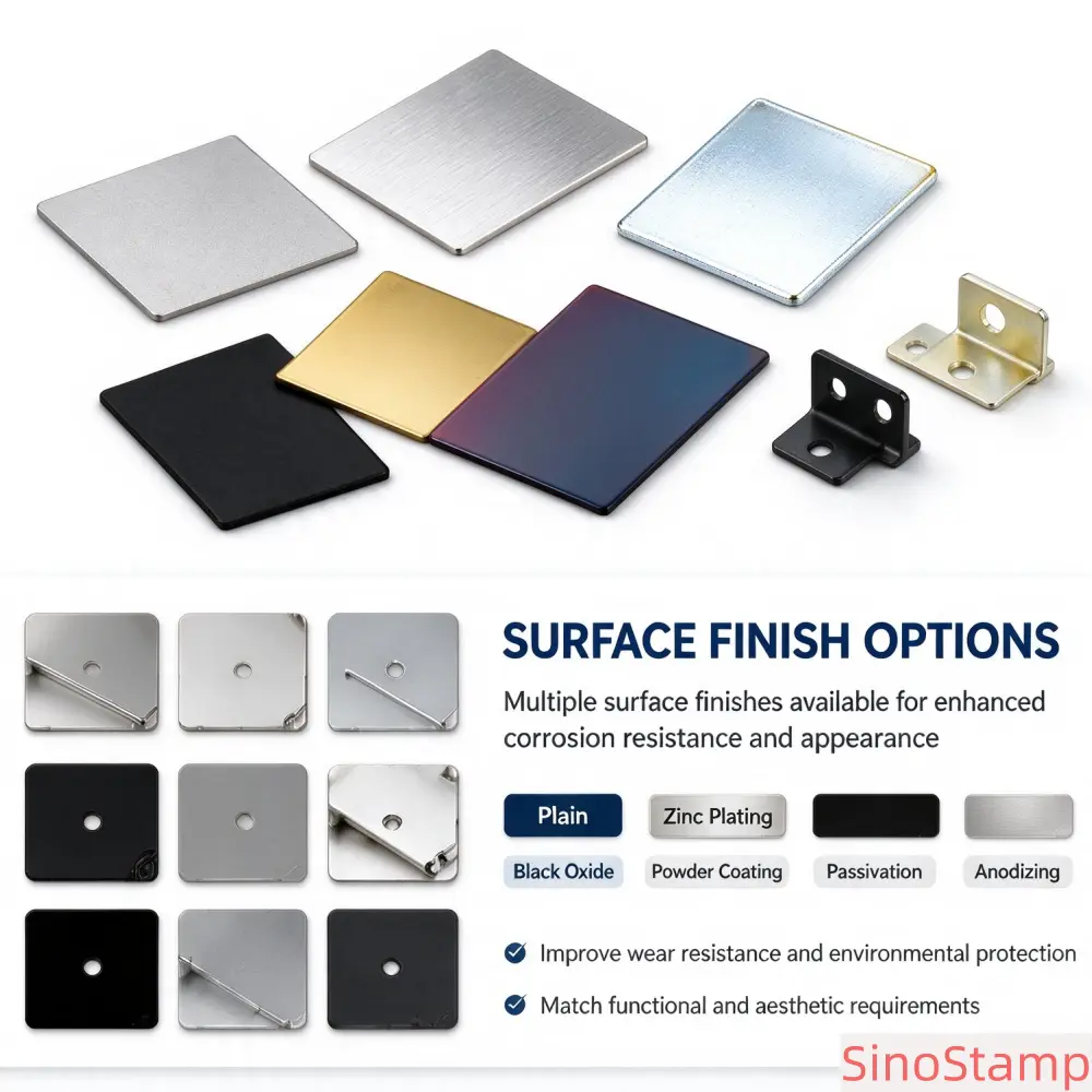
The four finishes listed for Sunny-1003 are zinc plating, nickel plating, powder coating and matte. These are not interchangeable appearance options. Each finish changes the electrical properties of the surface, the dimensional condition of the part and the corrosion mechanism, and the choice should be driven by the bracket's function in the assembly.
Zinc Plating
Zinc plating is the cost-effective corrosion protection for steel brackets in indoor electronic equipment. It provides a sacrificial zinc layer that protects the steel substrate, and the coating is thin enough that it does not normally interfere with the fit of a mating component. Zinc plating is electrically conductive, which makes it compatible with grounding functions, but the buyer should be aware that zinc electroplating has been associated with whisker growth in some applications, and a supplier quoting a zinc finish for a fine-pitch electronic assembly should be able to discuss the whisker risk and any mitigation[reference:13]. For brackets that will be powder coated, zinc plating or zinc-nickel plating can serve as a conductive base layer, but the powder coating over the top must be masked at the grounding zones.
Nickel Plating
Nickel plating provides a harder, more wear-resistant surface than zinc and maintains conductivity at the contact surface. It is selected for brackets that experience repeated handling, sliding contact or a visible wear surface, and it is also a candidate where zinc whisker risk is a concern[reference:14]. Nickel plating is more expensive than zinc, and its corrosion failure mode differs from zinc: nickel is a barrier coating rather than a sacrificial one, so a scratch that exposes the substrate does not receive the same galvanic protection that a zinc coating would provide. The drawing should specify the nickel thickness and, where relevant, whether a trivalent chromium top layer or a specific passivation is required.
Powder Coating
Powder coating provides the thickest protective layer and the widest color flexibility, and it is suitable for brackets that need a durable finish or a specific appearance. The coating thickness is typically in the range of 60 to 120 micrometers, which is substantially thicker than a plated layer and can affect the fit of close-tolerance interfaces[reference:15]. The more important consequence for an electronic bracket is that powder coating is electrically insulating. A grounding point that is fully covered by powder coating is not a grounding point at all; it becomes a decorative surface with no electrical function[reference:16].
The correct process for a powder-coated electronic bracket includes masking. The grounding contact areas, the threads and any tight-fit interfaces that must remain conductive or dimensionally clear are masked before coating, and the masking is removed afterward to expose the substrate or the conductive base layer[reference:17]. The same masking logic applies to threads: a powder-coated thread cannot accept a mating screw without cleaning or re-tapping, and the drawing should identify which threads and which surfaces are no-coat areas. Coating thickness around slots, hinges and clinch fasteners also requires control, because a heavy coating in these regions can cause interference during assembly[reference:18].
Matte Finish
Matte is a surface appearance rather than a distinct corrosion system, and it is normally achieved through the treatment or the additive in a plating or coating process. A matte finish reduces specular reflection and is selected for brackets that sit near optical sensors, visible interior surfaces or user-facing assemblies where a bright reflection would be undesirable. The underlying corrosion protection still comes from the plating or coating system beneath the matte appearance, so the buyer should confirm whether âmatteâ refers to a matte zinc, a matte nickel, a matte powder coating or a bead-blasted surface, and specify the corrosion performance separately.
Dimensional Control: Making ±0.05 mm Meaningful on a Drawing
The ±0.05 mm tolerance in the Sunny-1003 specification is a capability statement for critical dimensions, not a blanket requirement for every feature on the part. A stamped and bent bracket contains several categories of dimension, and they are not equally affected by the forming process.
The dimensions that normally justify a ±0.05 mm callout are the functional interfaces: the position of mounting holes relative to a defined datum, the center distance between a pair of locating holes, the location of a threaded or clinched fastener relative to the mounting face, and the flatness of a surface that seats against a PCB or a housing. The bend angle may also require a tight angular tolerance, but it should be specified as an angle with its own tolerance rather than converted into a linear ±0.05 mm callout on a flange length, because the two are controlled by different aspects of the process.
Dimensions that generally do not benefit from a ±0.05 mm callout include the overall blank outline, non-functional edge locations, cosmetic radii and features that are not part of the assembly interface. General tolerances such as ISO 2768-medium allow ±0.3 mm on lengths in the 30 mm to 120 mm range, and applying that class to non-critical features allows the supplier to concentrate inspection and process control on the dimensions that actually affect fit[reference:19]. When every dimension on a drawing is marked tight, the supplier may need to add operations, increase inspection time and reject parts for variation that has no functional consequence, and the quoted price reflects that added cost without improving the assembly.
The datum scheme is the mechanism that makes a tight tolerance inspectable and repeatable. For a formed bracket, the datum should be established on the formed part, typically from the mounting face or from a pair of holes that locate the bracket in the assembly. Dimensions that control the relationship between two bends should be taken from a common face rather than chained from bend to bend, because each additional bend in a chain compounds the springback variation and the tolerance stack[reference:20]. A drawing that establishes one functional datum and dimensions the critical holes and fastener positions from that datum gives the supplier a clear basis for tooling, inspection and first-article approval.
Quality Validation: From First Article to Process Capability
A first-article inspection confirms that a representative production-intent part meets the drawing. It records actual measured values for dimensions, tolerances, GD&T, material condition, thread and fastener features, surface finish and appearance, rather than a simple pass or fail[reference:21]. For a bracket, an FAI report that records a bend angle as a measured value such as 89.5 degrees is more useful than a report that records âpass,â because the measured value shows how much margin remains before the feature drifts outside the tolerance[reference:22]. The FAI sample should come from the initial production-intent run and should be selected according to an agreed sampling method, not simply the first part that comes off the tool.
First-article approval and process capability answer different questions. A supplier can pass an FAI on a bracket and still lack the process control to hold the same tolerance across a volume order. Cpk measures how consistently a stable process stays within the critical tolerance limits for a selected characteristic, and it is normally applied to the critical-to-quality features identified on the drawing rather than to every dimension[reference:23]. A Cpk value below 1.33 on a critical hole or a controlled bend angle is a signal that the process variation is consuming too much of the tolerance band, even if the parts measured so far are within specification[reference:24]. For a buyer placing a repeat order, the relevant quality evidence is not only the FAI report but the supplier's ability to show capability on the features that matter and a control plan that maintains them in production.
Material traceability and finish verification complete the quality picture. The material certificate should identify the grade and heat or lot, and it should be available for the batch used on the order. For plated and coated parts, the finish specification should state the coating type, the minimum thickness and, where relevant, the salt-spray duration and the acceptance criteria. These records are particularly important for brackets that carry a RoHS declaration, because the compliance of the finish depends on the specific process chemistry and not only on the base metal.
RoHS and Finish Compliance
Sunny-1003 is offered with RoHS compliance, but RoHS compliance in a metal bracket is a property of the finished part, including the surface treatment, not only the substrate. The RoHS directive restricts lead, mercury, cadmium, hexavalent chromium, polybrominated biphenyls and polybrominated diphenyl ethers, and a coating or plating process that introduces a restricted substance can make an otherwise compliant metal part non-compliant[reference:25]. Zinc and nickel plating processes are generally compatible with RoHS when the process chemistry is controlled, but the buyer should request a material declaration or test report that covers the specific finish and the specific supplier, rather than relying on a generic statement that âthe material is RoHS compliant.â Some plated finishes have historically relied on exemptions, and the applicability of an exemption depends on the finish and the end use, so the compliance statement should identify the finish and the basis for the declaration[reference:26].
For brackets that will be used in soldered assemblies, the finish also affects solderability and the lead-free compatibility of the solder joint. A tin-plated or nickel-plated contact area is generally more solderable than a bare steel or a powder-coated surface, and if the bracket has a solderable feature, the finish at that feature should be specified separately from the finish on the rest of the part.
Customization Scope: What the Drawing Can Define
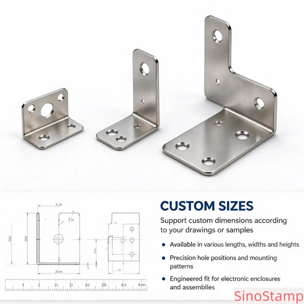
Sunny-1003 is an OEM and ODM bracket, which means the customization scope extends beyond selecting a material and a finish from a list. The drawing or the sample can define the overall outline and size, the hole pattern including hole diameter, position and thread specification, the bend angles and inside radii, the location and type of clinching or riveting features, the relief cuts at intersecting bends, the masking zones for grounding and threads, and the packaging and labeling requirements.
For an OEM project, the customer provides a complete drawing with material, thickness, dimensions, tolerances, datums and finish requirements, and the supplier reviews it for stamping and forming feasibility before quoting. For an ODM project, the customer may provide a preliminary design, a 3D model or a physical sample, and the supplier's engineering feedback covers bend radii, hole-to-bend distances, relief requirements, fastener selection and finish masking. This DFM feedback is the point at which many of the dimensional and finish problems described in this article are either designed out or locked into the tooling. A supplier who quotes a bracket without reviewing the bend and hole relationships is quoting a part that may not be manufacturable at the stated tolerance.
Applications and the Assembly Problem Each One Poses
PCB mounting brackets are used to support and locate a board within an enclosure. The critical bracket dimensions are the hole pattern that matches the PCB mounting holes, the flatness of the surface that contacts the board, and the height that positions the board relative to other components. A bracket that is dimensionally correct in the flat pattern but distorts during bending can introduce stress into the PCB when the screws are tightened, and over time that stress can cause solder joint fatigue or board cracking. The bracket drawing should control the flatness of the PCB seating surface and the position of the mounting holes relative to that surface.
Power supply brackets support and separate internal components while maintaining clearance for airflow and creepage distances. In these assemblies, the bracket may be part of the grounding path for a heat sink or a transformer frame, and the finish at the grounding contact must be conductive and masked accordingly. The bracket also needs sufficient stiffness to resist vibration, which may require a thicker gauge or a formed rib rather than a flat plate.
Communication equipment brackets sit inside modules where RF grounding and mechanical stability both matter. A bracket that provides a ground return path for a shielded module needs a low-impedance connection to the chassis, and a powder-coated bracket with an unmasked ground pad will not provide that connection. The material selection may favor copper or nickel-plated steel where conductivity at the contact is a priority, and the finish specification should identify the grounding surfaces as no-coat areas.
Household appliance brackets are typically cost-sensitive, high-volume stamped parts. The material is often tinplate or a plated steel, the finish is selected for indoor corrosion protection, and the dimensional focus is on hole position and assembly speed. In this application, the tolerance strategy should concentrate on the mounting features and allow general tolerances on cosmetic and non-functional edges, because over-specifying a high-volume bracket adds cost that the appliance program cannot absorb.
Packaging and Surface Protection in Transit
Sunny-1003 brackets are packed in anti-static bags with export cartons. The anti-static bag is relevant for parts that will be handled in an electronics assembly environment, but for a metal bracket the more immediate packaging risk is surface damage. A plated or powder-coated bracket that rubs against another bracket in transit can develop scratches, coating chips or contact marks that become corrosion initiation sites or electrical contact defects. For brackets with masked grounding areas, the masking exposes bare or plated substrate, and that exposed area is particularly vulnerable to handling damage and contamination. The packaging method should keep finished surfaces separated and should protect the grounding zones and threads from impact and abrasion. For painted or powder-coated parts, an interleaving layer or individual bagging may be appropriate; for bright plated parts, a VCI or anti-tarnish material may be needed if the parts will be stored before assembly.
Why SinoStamp for Sunny-1003 Brackets
SinoStamp's bracket production is organized around the relationship between stamping, forming and assembly function. The manufacturing scope covers precision stamping, bending, forming, tapping and riveting, which means the bracket can be produced as a single integrated part rather than as a flat stamping that requires a separate secondary operation at another supplier. The material range includes stainless steel, aluminum, tinplate and copper, and the finish options include zinc and nickel plating, powder coating and matte treatments with masking for grounding and thread protection.
The engineering value is in the drawing review. Before tooling is released, the bend radii are checked against the material grade and thickness, the hole positions are checked against the bend lines and relief requirements, the fastener selections are checked against the available panel thickness, and the finish masking zones are identified. These checks reduce the risk of a first article that meets the drawing dimensionally but fails at assembly because a hole moved during bending or a grounding point was covered by coating. First-article inspection reports and material certificates are available on request, and process capability data can be provided for the critical features identified on the drawing.
Information Required for a Bracket Quotation
To quote Sunny-1003 or a similar custom bracket accurately, the supplier needs the 2D drawing with tolerances and datum callouts, the 3D model where available, the material grade and thickness, the finish specification including any masking requirements for grounding or threads, the hole and thread schedule, the bend angles and inside radii, the fastener standard for clinching or riveting features, the estimated sample and production quantities, the required quality documents such as FAI, material certificate or Cpk data, and the packaging and labeling requirements. A drawing that identifies the functional datum and the critical-to-quality features allows the supplier to review manufacturability and quote a process that is capable of holding the specified tolerance, rather than quoting a generic stamping process and discovering the capability gap at first article.